NDT Inspection with 3D Scanning Ensures High-quality Cast Parts
Casting is one of the typical industrial manufacturing techniques, which involves pouring liquid material into a mold with a hollow cavity of the desired shape and then allowing the metal to solidify. The solidified part ejected or broken out of the mold is called casting.
Casting is well-suited for creating parts with complex shapes, which would otherwise be difficult or uneconomical to manufacture using other methods. Heavy equipment such as gear housing and engine pistons can be easily cast in the required size rather than creating them by joining several small pieces.
Precision casting, an advanced process in machinery manufacturing, is widely used for producing ferrous and nonferrous metal parts. It produces net shape parts with a good surface finish and dimensional accuracy. There are different types of casting processes, including sand casting, investment casting, die casting, lost foam casting, and more.

Image source: Casting Photo by Ludomił Sawicki on Unsplash
NDT Inspection of Cast Parts
Generally, an inspection of the surface of the casting can be carried out with the naked eye or with a magnifying glass or microscope. This method can only detect surface defects such as blow holes, fusion, swellings, external cracks, and mismatches. Almost all castings undergo some level of visual inspection.
Castings need to be inspected thoroughly To ensure high dimensional accuracy. A non-destructive test (NDT) can be used to examine castings without causing damage to the product. Such tests can detect defects that negatively affect the material’s strength.
Comparing the blank with the digital 3D model is used for reprocessing the surface with large deviations, which will facilitate the casting reaching higher standards and reduce the workload.
However, it is difficult for traditional methods to precisely calculate the deviations of complex casting and mold. Therefore, efficient and accurate 3D NDT inspection is significant to mechanical manufacturing.
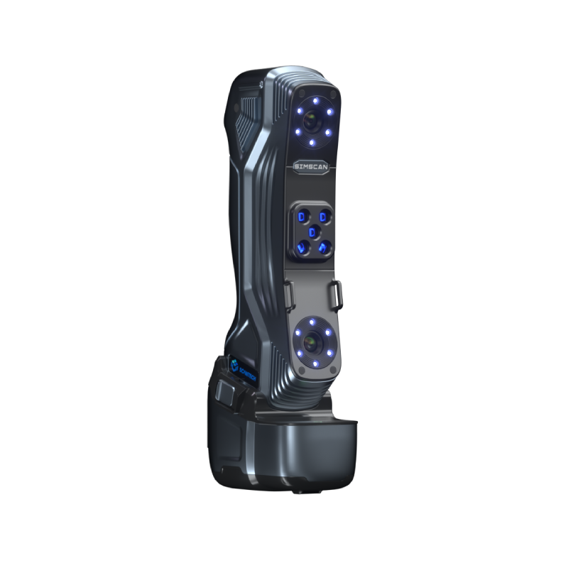
Scantech’s offers portable 3D scanners, including KSCAN-Magic and TrackScan, as well as comprehensive 3D scanning solutions to perform non-contact measurement for cast parts ranging from small to large scales.
Compared with the contact measurement technology, it can capture the contour of complex surfaces like free-form surfaces more quickly and completely and can reflect the deformation trend comprehensively.
What does the customer need?
Compared with the original 3D model, casting usually has obvious deviations, and the shape is irregular. The traditional inspection method is not easy to operate and time-consuming, hence, it is hard to obtain comprehensive and intuitive inspection results. Except for detecting deviations, the customer also needs to know the specified geometric tolerances.
ScanTech 3D Solution
To get the full 3D data of the casting and concave model cavity, we use HSCAN 3D scanner to finish the whole inspection. By using 3D software ScanViewer to fit and align the data, we will obtain comprehensive deviations and geometric tolerance values.

3D Scanning Process
Step 1. attach markers on castings
Step 2. use HSCAN 3D scanner to scan castings and molds
Step 3. data fitting and alignment for 3D inspection
Step 4. product optimization based on inspection data
Molds Scanning
Object 1. casting connecting rod
Time cost:
Attaching markers: 2 minutes
3D scanning: 5 minutes (resolution set to 0.6mm)

Point cloud data

Stl data

Color map
Object 2. casting piston
Time cost:
Attaching markers: 2 minutes
3D scanning: 5 minutes (resolution set to 0.6mm)

Point cloud and stl data
 Color map
Object 3. concave die
Time cost:
Attaching markers: 2 minutes
3D scanning: 4 minutes (resolution set to 0.6mm)

Point cloud data

Stl data

Color map
Geometric tolerance measuring
The customer requires to measure the distance between the two cone axes on the concave die. The method is to establish features between axes and the surface of the die, and respectively create point features at the intersection. Finally, the distance can be calculated by measuring the length of two points.

Standard geometric tolerance value

Measured geometric tolerance data
3D laser scanning technology greatly improves the speed and quality of the inspection comparison. Handheld 3D scanners efficiently overcome the shortcomings when measuring the deviations of the irregular castings.
For more cases about molds inspection, please read:
3D Mold Scanning – A Revolution for Machinery Manufacturing


 All Products


 en
en 


